Friday, 3 January 2020

ISOMEC Millenium Repair - No Heat after warming up


It was the most alarming development. Warm up the machine early in the morning, make a "cuppa" and then come back an hour later for another, and COLD is the only word to describe the machine. It got worse. Specifically, the symptom is that neither the READY or HEATING lights are lit. It took me weeks to shy up to diving in, mostly out of sheer laziness from the Christmas break. Yesterday I got to the bottom of it. Part of the issue is language. The Isomac Millenium circuit diagram is really a wiring guide and all the twists and turns on the diagram make it hard (for me) to figure out what is going on with the logic.  I re-drew it into a more classical schematic format as it is the "language" of electronics and wiring I am most comfortable with. You will notice I stopped once the problem was solved. Perhaps this will help someone else with this problem.

Solving the issue was not cut and dried, and it took a bit of creative hardware management to remove the water reservoir tray and boiler cover, placing the water inlet filter into a measuring cup full of water.

Here follow the wiring diagram and my own schematic:


The reader will notice that this schematic is missing the "water level" sense wiring.  Only a portion of the GIEMME controller is diagramed, that being the two relays.  Note that the common portion of both relays is connected to the Line level voltage through the Main Power Switch.  The heating element relay is solid-state and I noticed that there was no heat transfer paste on the underside of it.  The bottom of the relay and the base of the coffee maker were cleaned of corrosion from a leaking gasket on the boiler, the heat transfer paste applied and relay affixed.  The control voltage was noted to be 120VAC and the relay was actuated by pulling A2 to ground through the NC contacts of the Pressure-stat.  The Green Ready light is connected to the NO contact on the Pressure-stat, closing when the boiler is at operating pressure.  When the machine failed, both lights were extinguished and the boiler pressure gradually reduced to zero.  A voltage check showed that Pin 2 of the Giemme had mains voltage on it, but Pin 5 did not.  It was determined the problem was within the Giemme controller.

At $192 USD replacement cost, I decided to remove and inspect.  I could not make matters worse if I broke it further.   I spent several hours setting up a test jig for the Giemme and powering and watching it fail.  The symptom was repeatable in minutes now and it appeared my removing it from the machine had exacerbated the failure issue.  I powered the Giemme with a 1 ampere fused autotransformer to facilitate slowly raising the input voltage.  Looking back over the repair sequence, it appears that without the sensor probe and other loads connected, the Giemme was "timing out" and releasing the relays.  I was interpreting this as the fault manifesting.  I changed the bridge rectifier, then suspected a short in the transformer.  A suitable replacement was found in my junk drawers, scavenged from an old "wall wart" power supply.  As a general principle with old electronics, I reflowed (nice term for re-soldered) all connections on the two boards that comprise the Giemme.  The bench test was OKAY.  It had stopped "timing out" after two minutes or so.  I had somewhat inadvertently repaired the device!!  After removal, the secondary winding of the transformer was reading open.

Post repair, I found a circuit diagram for the Giemme controller while searching for the correct replacement for the transformer:


I also found a web post of others with the same problem:


https://www.home-barista.com/repairs/giemme-controller-bad-transformer-t46064.html

If nothing else, this supported my findings.

and lastly, some close-ups of the errant transformer:


Continuing the search, I found a supplier of the transformer:

http://www.nordtek.com/index.php?m=products&id=82

I have enquired if the transformer is available though the thought of disassembly and re-assembly just for the sake of a so-called proper transformer do not excite me.  I will post further information when and if I have it.  73  de VE2GYA

Friday, 27 September 2019

Yet another multiband dipole design


Our house is on a corner lot so it wouldn't be appropriate, even for me, to put antennas in the front yard, Hi Hi!!  So the roof is the next best place.

Sunday, 4 August 2019

N3804X Last three hours of flight dodging storms.

2019 August 4th

Review of publicly available material pertaining to the reported crash of N3804X Beechcraft Bonanza.  I was wondering how a pilot could stray over 350 nm off course purportedly looking for a break in a frontally generated line of thunderstorms.  What follows are some images, the first is the flightpath as reported by FlightRadar24, and the rest of the flight paths are from ADSBexchange.com, a freely accessible site for everyone, lightning information is from the Blitzurtung lightning site.

I have my own thoughts, but I will let you create your own conjecture from the following.  Understand that the pilot was within 50nm along the flight of about 20 METAR reporting airports and   likely 30 perfectly serviceable runways along the flight to the crash. It is hard to understand what pushes a person to their death trying to get home when there are so many safe options.  What could have been so important, so critical, that they would risk skirting thunderstorms for hundreds of miles?  There is great wisdom to the phrase:  "Land and Live."

One contributing factor could have been that the Noranda radar site in Canada was not operational at the time of the crash, so weather in the area of the crash was not serviced by radar.  Also, NEXRAD services extend just a bit into Canada so that would not be available either.  Then add in that conditions changed to NIGHT conditions in the 30 minutes or so leading up to the crash.  What is that other saying I have heard and recited so many times?  "The average pilot can manage one or two challenges concurrently in a flight, but the third one can kill you"  See:  http://www.langleyflyingschool.com/Pages/CPGS%20Pilot%20Decision%20Making.html

The Canadian Transportation Board has begun an investigation into the crash.  That file is located at: http://www.bst-tsb.gc.ca/eng/enquetes-investigations/aviation/2019/a19q0128/a19q0128.html

Method:
In the following images, the Blitzurtung lightning data was overlain upon the flight path in one hour increments. The imagery from Blitzurtung and Flight Radar24 was first scaled and rectified in Photoshop to line all geographic points up. Therefore each image represents what was occurring at that time.  The lightning imagery is colour coded:  Red is past two hours, white is past 15 minutes, yellow is in between.

Flightradar24 showed this as the last few minutes of the track for N3804X


Flight Aware lists this as the last flight of N3804, from KDXR to KOSH.
https://flightaware.com/live/flight/N3804X/history/20190714/2008Z/KDXR/KOSH/tracklog


This first image shows the flight path, beginning just before 20:00 UTC on July 29th.


Here is the storm picture at the time of departure.


Here is the storm situation at one hour into the flight.  It could be that the pilot was heading for the break in the storms just ahead of the current position.


At two hours into the flight, something prevented the pilot from turning South East through a break in the lightning and heading down to New Hampshire. I believe, but do not know for certain, that that was the destination for the flight.  I could not find radar data for this time, but likely there was still a lot of build-up and CB in the region.


Three hours into the flight and you can see some curves in the last flight path, likely staying clear of storm cells.  The last reported point is seen clearly just a little bit north of the current lightning reported.  As reported in multiple news sources, the aircraft crashed and the pilot was killed in the crash.  The elevation was reported at 7825 at this last point.

So what do you think went on?  What lesson(s) can be learned from this crash?  The pilot gave their life in this flight, so I feel a responsibility to learn something from it.


Copy from Kathryn's Report:


Monday, August 5, 2019


Beechcraft V35B Bonanza, N3804X: Fatal accident occurred July 30, 2019 in Senneterre, Quebec, Canada

Bruce Cameron

Federal Aviation Administration / Flight Standards District Office; Bradley


Aircraft crashed under unknown circumstances.


Two Three Echo Ltd


https://registry.faa.gov/N3804X


Date: 30-JUL-19

Time: 01:37:00Z
Regis#: N3804X
Aircraft Make: BEECH
Aircraft Model: 35
Event Type: ACCIDENT
Highest Injury: FATAL
Aircraft Missing: No
Damage: DESTROYED
Activity: PERSONAL
Flight Phase: EN ROUTE (ENR)
Operation: 91
City: SENNETERRE
State: QUEBEC

Those who may have information that might be relevant to the National Transportation Safety Board investigation may contact them by email eyewitnessreport@ntsb.gov, and any friends and family who want to contact investigators about the accident should email assistance@ntsb.gov. 


Beechcraft V35B Bonanza, N3804X

A small American plane that went missing Monday near Senneterre has been found. The pilot, who was the only person on board, was found dead amid plane wreckage in dense forest in northwestern Quebec.

A Canadian armed forces helicopter sent to search for the Beechcraft V35B Bonanza found it around 7 p.m. Friday in Quebec’s Val d’Or region, about 525 kilometres northwest of Montreal.

Capt. Trevor Reid says the air force, provincial police and the Transportation Safety Board of Canada are investigating.

“It was found in very austere terrain, dense forest and large trees,” he said. “The pilot was found with no vital signs.”

About 100 rescuers from the RCAF, Quebec’s provincial police and other agencies participated in the search operation.

“We hope that this discovery helps the family with its grief and our thoughts are with them during this difficult time,” chief of operations John Landry said in a statement.

Six armed forces aircraft, a Coast Guard helicopter, a Sûreté du Québec helicopter and six Quebec rescue aircraft assisted in the search, as did planes from the Civil Air Search and Rescue Association flown by volunteers.

The plane left an airport in Wisconsin, flying toward Danbury, Connecticut. The pilot deviated from his flight plan toward the north because of weather.

“We know he turned north to avoid a very large storm,” Reid said Saturday. “What remains unknown and what is now part of the investigation … is how he came to be that far north.”

Air traffic control lost contact north of Senneterre, in the Abitibi-Témiscamingue region.

The flightradar24.com website, which tracks active flights, indicates the plane, with callsign N3804X, took off at 2:55 p.m. Monday from Wittman Regional Airport near Oshkosh, northwest of Milwaukee. It proceeded northeast over Lake Michigan and Lake Huron, passed between Malartic and Val-d’Or and flew north to Senneterre before turning northwest.

The air force did not identify the pilot.

Original article ➤ https://montrealgazette.com

6 comments:


Anonymous said...
Bad news and strange. RIP
Anonymous said...
He spent 2+ hours at 11,500'. I wonder if his plane was equipped with oxygen or if he had a malfunction with it leading to confusion and poor decision making. Based on the FlightAware track it looked like he was headed to YUY airport but then turned east. I wonder if he finally ran out of fuel?
Anonymous said...
11 500 for having done that many time won't affect you. Just a small like hangover went you land. Unless he was a smoker. Could be worse. We don't know is the last communication. Could be interesting to know. Might be unconscious and just run out of fuel. The final path of the plane makes it look like free falling.
Anonymous said...
"He spent 2+ hours at 11,500'" Insightful observation. 11,500' is high enough to make a person sleepy. This flight took off a few minutes before 3PM. The plane would've run out of fuel perhaps 5 hours later, getting well into evening. Drone of the engine. Sun setting behind the airplane. Fairly remote stretch of the trip and perhaps not a lot of chatter on the radio.
Anonymous said...
Well, he dodged the storm. This reminds me of the guys in Maine who became lost while moose hunting. They complained to their guide "Hey, you said you were the best guide in the whole US!" He replied "I am! But I don't think we're in the US anymore!"
Anonymous said...
High altitude and long duration flight. No supplemental oxygen even at 11000 feet is a recipe for disaster. Use it above 8000, every time. No oxygen, then stat below 7500. Simple as that.

Tuesday, 17 April 2018

AP8 Cushcraft repair

Additional information added April 18th after disassembling the two resonator section.
and further update May 21.  All resonators serviced and tuned.

Here is a quick overview of the damage to my AP8 multi band vertical antenna damage after an ice storm earlier this week.   Note the new to me RCA laboratories transistor checker from my cousin Bob Balcaen in the background.  I used this in the late 60's and 70's as I struggled to understand semi conductors. 


This is the third tank circuit up from the bottom of the antenna, Which would be for the third resonant band, or 15 meters.  I believe.  The fibreglass insert failed.  Small wonder given the load of ice and high winds we had.  The resonators are for 40m, 30m, 20m, 17m, 15m, 12m, 10m. 80 meters does not have a resonator as it uses the entire antenna.

Here is the manual, or a scan of it, for the AP8.  Thanks to Bruce Lauer, VE3QX, for scanning his manual for me.  The manuals are long out of print.  it is a 3 meg file.  Not sure if both pages are included, but this is the tuning and assembly instructions.

Now it is off to Bob Morton for guidance and parts!!

Here are some shots of it bent over.  What a sorry sight, and it got worse as the day wore on.  By mid day the top was 90º bent over and at 1pm it snapped.  3/4" of rime icing.  The guys were nylon, 3/16' and once loaded up with ice dragged the antenna down.  My 160 meter vertical in the background did just fine.  High winds from the East just pushed the AP8 over.  My dipoles were just fine too, as the smaller the wire, the less ice collects.


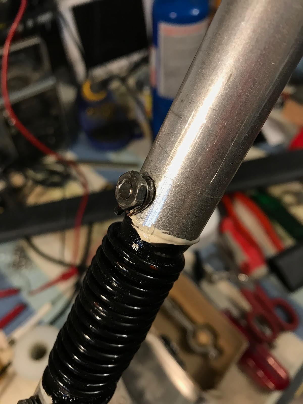
And now the disassembly of the broken section.

Turns out it is one piece of fibreglass tube for the two resonators, so the two ends can come off, but not the middle section unless I cut the fibreglass tube.  Not ready to do that now.  Also, the aluminum wire used for the coils is quite springy, and I doubt I will be able to hand wind it in place.  I may look for some similar gauge copper magnet wire for the rebuild.

The two resonators before disassembly.  The heat shrink used was still intact but all the screws holding the coil wire to the tubing were badly rusted.  The tar holding the coils in place was still a little pliable after 30 some years, and stunk just like creosote treated railway ties. 
The fibreglass tube was easily pounded out with a punch and just a light hold of the vise. 
Both the top, and bottom pipe sections removed.  


Coils removed.  You can just see a bit of a swale in the section.  The fibreglass failed badly.

Dimensions:

Fibreglass  0.75 inches OD
Pipe sections:  .75" ID  0.88" OD
Wire:  after numerous measurements I settled on 0.115"

Next steps:  Measure up the rest of the pipes I want to replace or enlarge and start looking for a source for the fibreglass rod required.  
May 21st.  Time to catch up the blog.  Much has happened and I am ready to put AP8 back up on the roof for final tuning.  It has been many evenings and weekend hours to get it to this point.  Here follows the process.

Bob Morton of Maple Leaf Communications proved an invaluable resource in rebuilding the antenna.  Aside from having all of the bits and pieces I needed IN STOCK, he recounted that designing and building the AP8 was his first job working for Cushcraft way back when.  Wow!  I am talking to THE authority on the AP8.  One comment he made was that his initial design used heavier pipe and fibreglass but the company wanted it light and inexpensive so that was what was built.  Light and inexpensive.  I want to talk more about this later, but now back to the antenna repair.

As it was so badly bent over, I decided to replace what pipe I could without rebuilding all the resonators, they are SO much time and effort to build.  It definitely gave me insight into the effort that went into designing and building these, and other antennas.


Here is my parts list, I had a couple of things wrong, and sorted it out later:

1 1.25" 4' tubing Swaged to 1.12" OD at top (the second tube up in the antenna)
2 1" 4' Tubing
1 0.38" 4' Tubing
1 0.88" 4' Tubing
1 0.5" 4' Tubing

8 1" Screw clamps, SS
2 1.25" Screw clamps, SS
2 1.75 Screw clamps, SS

14" 0.75 Fibreglass tubing
14" 0.5 Fibreglass tubing (to be inserted into .75 and resin added to affix)

32' #12AWG Coated magnet wire

16 ¼" Caps, vinyl tubing (should have been 3/8")

24 Suitable SS screws for compressing coil ends against tubes

1 1.25" 4' Heavy Duty Heat shrink to seal coils

1 package of suitable crimp eyelets for copper magnet wire (not needed, just bent the wire into a loop and tinned)

1 3/32 300' Dacron guy line 

1 small container of suitable corrosion inhibiting goop (butter it's not?)

1 pint   container(s) of suitable resin for affixing fibreglass to tubing.  (ended up purchasing tubes of epoxy suitable for fibreglass from local hardware store) 
I will likely coat the coils with it too. 


Yes, many espressos consumed in the rebuilding of this antenna.  Look, there is a spiral galaxy in my coffee!  
Here is the frame for the 15-17m resonator section resting on a level surface (complete with V channel to ensure everything stays aligned, was I ever lucky to find this in my garage!) Prior to this I glued the two fibreglass sections together, inserting the smaller one into the larger one with a mess of epoxy glue (with "use on fibreglass" written on the label) What a mess.  Don't do it on your electronics bench.  I had glue on the floor, the soldering iron, the mat and a couple of tools.

Then, I cut the pipe to match the old one, and glued it in place.


Drilling a 5/32" hole and using the hardware from Maple Leaf proved simple, as was winding the coils.  Copper is such a treat to work with.  The connections were disassembled, tinned with LEAD based solder and reassembled.  Looks not too bad for an amateur!

I should have bought the 3M coating material from Maple Leaf, but the total bill for parts was rising, so I settled for a small can of Liquid Tape fromStarBrite, an American firm.  Seemed to work okay.  


A measurment of one of the coils.  The paint on tape did not change the inductance a measurable amount. 


Here is a closeup of the 10m coil.  What a mess.  The screws originally used were steel and corroded substantially, so badly that there were large cavities in some of the screws.  I removed all of these from all of the coils (7) cleaned them up, drilled a 5/32 hole through to the other side and used the # 8  stainless steel nuts and bolts to re attach.  I used a 1/4"  torque wrench to tighten them all to 25 inch-lbs.  


Corrosion.  It became apparent that the corrosion of the screws occurred because of moisture INSIDE the antenna, not from the shrink boots leaking.  When I reassemble I will study the joins and look for ways to limit the water leaking inside the tubes.  I think the slats cut in the tubing that allow the clamps to work are the likely culprit.  Perhaps I will heat shrink them too, or drill little "vent" holes tilted down to allow airflow if sealing the joints is not possible.  More on this point later.


Cleaned up (at least the contacts) and ready for new NTE 3:1 lined heat shrink.  Curiously, this heatshrink lowered the coils about 1mhz in tuning.  More on that later.  The 1.5 inch heat shrink was perfect for the 10 and 12m coils, but a little big for the rest of the coils.  Next time (Hah!) I will order some 1.25" heatshrink for the other five coils.


The 30 m and 40m coils were of copper wire.


A finished resonator before tuning.  A word of caution about working with the capacitors.  If you are wanting to change the shrink tubing, as I did, use a sharp knife to cut off what you can.  The polypropylene used for the dielectric melts at a low temperature.  You will distort or have it fail if you get it too hot.  Use just enough heat to shrink the tubing and then stop.  Do not use heat to remove the tubing, as i did, as you will likely wreck the tubing, as I did.  Use a knife.


I almost did not want to know what the tuning was, as it would mean changing the capacitance or even worse, changing the coil winds, which would require obvious extra effort as I had sealed them up already.  The 40 and 30 meter coils were affected by the new heat shrink the most.  While I did not measure it, it felt about twice as heavy as the original shrink tubing.  Here is the theory of operation of the antenna, best effort.  I am still wrapping my head around it, but at resonance, the antenna ABOVE the resonator is mostly excluded from the RF circuit.  In essence, the L-C circuit presents a HIGH IMPEDANCE to rf current flowing through it.  Below resonant frequency the L-C presents a largely inductive image on the antenna and is simply viewed as a coil of wire and becomes part of the radiating element.  Above resonance, it presents a largely capacitive image to the antenna.  

Obviously there was a tradeoff in the design as the L-C combination needs to both: resonate at the desired frequency and provide enough impedance (winds of coil) to work on the next lower band.  The 40 meter coil pictured below was affected the most by the shrink tubing, dropping 1.5 mhz in frequency.  I managed to tune it by pulling the rods out of the capacitors to about 1/3 of what they were initially inserted.  We will see how it works once installed back up on the roof.  If need be, I can disassemble and remove 10% of the 40m coil and retune.  

Note the test lead wrapped around the centre of the coil and a 50 ohm resistor inline.  I put the 50 ohm resistor in line as I didn't want to work the meter at an unusually low impedance.  I have no empirical data that this makes a difference but it didn't hurt.  This seemed to work well, and both my Comet and YouKits tuners worked well.  The YouKits draws a little graph, so you get to see the switchover point of inductance to capacitive reaction (I think).  Bob Morton's advice was "Tune a little low for the part of the band you want, then adjust the pipe lengths. "  


I tuned the coils as follows:

40m 6.90 mhz (the top resonator of the antenna)  (major reduction of capacitance)
30m 10.0 mhz  (did not have to change capacitance)
20m  13.8 mhz (did not have to change capacitance)
17m  17.7 mhz (did not change capacitance)
15m 20.86 mhz (reduced capacitance a little)
12m 24.6 mhz (reduced capacitance a little)
10m 27.9 mhz (reduced capacitance a little) (the bottom resonator of the antenna)

I wrote the resonant frequency on each coil to ensure they get back into the correct order.  My hunch is that I had the 20 and 30 meter resonators reversed and the antenna never worked at all on 10m, and not so much on 20m.  Perhaps it will be different after all this work.

The dual coils both show up on the antenna analyzer so much so that it is hard to tell which resonator you are adjusting.  Bob Morton suggested running a short jumper lead across the L-C circuit you are not using to dampen it.  This helped a lot.  The pipe on the end of the L-C also changes the tuning a bit so this ended up being a best effort.  I will find out how close I got once installed and operational.


At this point in time, all the pieces are scattered around my shop.  I need to prepare the tubing and  put back up on the roof, maybe moving it a few feet to the east.  I have new guy line, and am hoping it will not stretch as much as the old.  


PAL 500 Power Amplifier